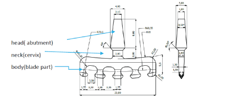
Figure 1: Geometry and dimensions of the blade implant for FEA.


Kučera J1 Lofaj F*2 Šimůnek A3 Németh D2
1Faculty of Medicine, Department of Dentistry and Maxillofacial Surgery, Pavol Jozef Šafárik University, Košice, Slovak Republic*Corresponding author: Lofaj F, Institute of Materials Research of SAS, Watsonova 47, 04001Košice, Slovak Republic, Tel: +421557922461; Fax: +421557922408; E-mail: flofaj@saske.sk
The applications of blade endosteal dental implants (BI) are justified in the cases of significant bone resorption of the alveolar ridge of the distal edentulous areas of the mandible and when the use of screw endosteal dental implant (SDI), osteotomy or augmentation do not bring long-term solutions. The aim of this work was a finite element analysis (FEA) of the stresses in BI and in the adjacent bone after immediate and delayed loadings in the atrophied bone of mandible. It was found out that von Mises stresses exceeding Ti6Al4V strength were generated in the neck of the existing commercial BI regardless of the level of osseointegration. The modifications of BI dimensions and shape were required to prevent locus minor and to guarantee their long-term stability. Osseointegration caused only small differences in the value of maximum stresses in the cases, when modified BI was applied in the free-standing abutment indications. Involvement of modified BI in the framework system with tooth or SDI caused reduction of maximum von Mises stresses well below the yield strength of Ti alloy and that of compact bone both in immediate and delayed loading cases. The work emphasizes the benefits of BI for unconventional solutions in the treatment of extreme atrophies of the residual ridge crest distal parts of the mandible.
FEA, Blade implants; Stress distribution; Framework system
Optimal implantation treatment in the distal edentulous atrophied areas of the mandible often encounters anatomical limits. Short implants (≤ 6.5 mm) are most often used [1-3], but their application is limited by the width of the residual ridge crest (often <2.5 mm wide) and by the distance from the course of the inferior alveolar nerve. Their use also carries risks of the remission of the marginal edge of the bone, and/or failure due to an inappropriate intra/extraosseous length ratio [4-6]. The alternative solutions include osteotomy techniques [7,8] and vertical and horizontal ridge augmentation. However, in the latter case, bone volume decrease, or even complete loss of augmentation were often observed over time [9,10]. Another possibility is the use of blade implants (BI). The first work on BI was published in 1954 [11] but their overview was published only in 1968 [12]. BI brought significant novelty in the morphological and indicative development compared to the existing implants. Later authors [13-16] focused on BI shape optimization. In late 1970s, BI was widely used especially in the indications of narrow residual ridge and atypical sponge-shaped distal alveolar process of the mandible.
However, the applications of BI declined in the 1990s, mainly because of the legal aspects of their categorization compared to SDI. In the next decade, interest to BI re-appeared again. The studies at that time reported positive results of long-term stability of BI [17] and their successful use as a non-standard solution in limited anatomical indications [18,19]. BI provides additional possibilities as a replacement of failed SDI [20,21], in progressive piezo surgical protocols [22] or on the clinical evaluation of their long-term stability, histological and X-ray confirmation of the quality of osseointegration [23], which is also affected by immediate loading [24]. The success rate of BI in such indications was up to 93.4% [25], which was comparable to the success rate of SDI. Another possibility would be the modification of shape of BI and adjustment of surgical protocol, e.g. Enosseous Distal Extension (EDE) blade implant technique [26].
The influence of stresses generated by occlusal forces on BI body and on the surrounding bone was considered based on mathematical modeling by Finite Element Analysis (FEA) method only starting from early 1990s, though already the first works from 1978 identified the stress concentration in the neck region BI [27] and its dependence on BI shape. The most significant drop of tensile stresses in the neck area of BI was found in BI with subperiosteal protrusions [28]. Ismail YH, et al. [29] demonstrated the stress concentrated not only in the BI neck, but also in the adjacent compact bone. Cook SD, et al. [30,31] monitored the influence of BI material parameters and shape changes on the stress in the surrounding bone. It was found out that the shortening of the blade part of BI caused increase of tensile stresses in crestal compact bone up to 50 %. The magnitude of the stress was also influenced by the properties of the BI material, especially by Young's modulus. Hashimoto K, et al. [32] demonstrated that bending of the supraosseous part of BI increased tension in compact bone. However, the computing capacity in FEA in 1990s (the number of finite elements was often only several thousands) limited the accuracy and relevance of the results in comparison with the current FEA capabilities [33].
The increase of computing power combined with the progress in CAD/CAM technology (Computer-Aided Design/Computer Aided Manufacturing) [34,35], and selective laser sintering (SLS) promote also customization and optimization of BI shape as well as its production for individual anatomical conditions, especially in the case of elderly patients. Indeed, Mangano F, et al. reported successful application of CAD/CAM customized BI-s from Ti6Al4V by SLS technology in the extremely atrophied alveolar ridge of the distal edentulous areas of the mandible after immediate loading [36,37].
The FEA optimization of BI shape is generally aimed at the reduction of stresses which could cause implant and/or bone failure. According to the results in [29-33] as well as in our study on stress distributions in mono- and bi-cortical implants, the compact bone carries up to 90% of the occlusal load and cancellous bone only 10% [38]. Thus, FEA optimization should be focused mainly on the maximum stresses in the neck of BI and in the adjacent cortical bone. However, the indications of a free-standing BI are relatively rare. In the demanding anatomical dispositions of an edentulous mandible, a fixed partial denture replacing the segment resp. the whole dental arch, is often necessary. Such implant supported dentures connecting SDI with one or more teeth in the interforaminal area, or with another SDI, were clinically tested in the absence of teeth on significantly atrophied mandibles [39-41]. For instance, Lanza MD, et al. [42] investigated fixed partial dentures connecting one SDI with one or 2 teeth under a uniform vertical load of 100 N. Maximum van Misses stresses were generated in the pontic-implants connection area and bone in the implant neck. However, the stress distributions in BI have not been analyzed by FEA in fixed partial denture (on another implant or tooth) up to now. Therefore, the aims of the current work involve not only the FEA evaluation of the maximum stresses in standard BI after immediate and delayed loadings but also the optimization of BI shape for their reduction in free-standing case as well as in the framework with tooth or standard SDI applicable to highly atrophied mandibles.
FEA was made on a standard blade implant based on a commercial certified implant (type MTI L01, Martikáň, SR, CE No 2017-MDD/ QS-026(ISO9001)) with the geometry and dimensions specified in Figure 1. It is indicated for atrophied distal edentulous parts of the alveolar bone of the mandible with a minimum ridge height above the canal is more than 6 mm and a crest apex widths more than 3 mm. The values of Young's modulus and Poisson's constant used in the calculation correspond to the properties of Ti6AI4V, Grade 5 alloy (Table 1).

Figure 1: Geometry and dimensions of the blade implant for FEA.
| Compact bone | Cancelous bone | Implant Ti6Al4V Gr.5 | Cement | Dentin | Parodontal ligaments | |
| Elastic modulus, E [MPa] | 13,7 × 10³ | 2,3 × 10³ | 1,14 × 10⁵ | 14,0 × 10³ | 18,6 × 10³ | 170 |
| Poisson‘s ratio, µ [-] | 0,3 | 0,3 | 0,3 | 0,35 | 0,31 | 0,45 |
| Yield stress, σY in compression and in tension [MPa] |
41.8 ± 19.4 – 176.3 ± 13.1 [46] |
- | 880-920 [46] | - | - | - |
| Strength, σu/in compression and in tension [MPa] | 53.0 ± 10.7 – 204.0 ± 11.2 [45] |
- | 900-950 [45] | - | - | - |
Table 1: Material properties of individual elements of the system used in FEA calculations. Material properties of compact and cancellous bone and blade implant (E-Young's modulus-corresponds to the ratio between stress and elastic deformation, respectively to the stiffness of the material; μ-Poisson's ratio - indicates the ratio of relative elongation and narrowing under tensile loading of material, σu -strength (ultimate tensile strength)-value of stress at which the failure of material occurs, σY -yield strength-corresponds to the stress at which the transition from elastic to plastic deformation occurs; for brittle materials, the value of σY is close to the value of σu).
Based on literature sources and our earlier works [38,43], the distal edentulous areas of the mandible with a significantly atrophied ridge were represented by a homogeneous isotropic 3D model of the mandible with an overlap into the premolar region (Figure 2). The cross-section of the model mandible had a trapezoidal shape with a crestal width of 5.0 mm, width of the basal part of 12 mm, height of 15 mm and cortical bone thickness of 2.0 mm. The length of the model was 33 mm (Figure 2a). The total height of the model was 26.4 mm. The model of mandible corresponded to the state of extremely atrophied bone with a density corresponding to grade D2 according to Misch scale [44-46]. Material parameters of cortical bone and cancellous bone are given in Table 1.
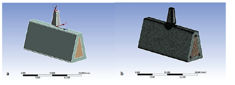
Figure 2: a: Simplified 3D model of BI in the distal area of the mandible and vectors of forces acting in individual directions at an occlusal force of 256.37 N; b: Division of the BI/mandible system by a tetrahedral finite element network necessary for the calculation of the stress distribution.
BI was located in the distal part of edentulous alveolar process in the area of the 1st molar. The implant was loaded with an occlusal force of 256.37 N at an angle of approximately 69.5° to the occlusal plane (Figure 2a). The magnitude of the force was the same as in the experimental works of Mericske-Stern [47,48] and other authors [49- 51]. Our previous work on stresses in mono- and bicortical implants under analogous load showed, that the maximum forces required to reach the yield strength at the cortical bone thickness of 2.5 mm, were in the range of 250 - 410 N [38]. Since BI-s are indicated for extremely atrophied alveolar ridges in the molar region of the mandible with the cortical thickness of only 2 mm, the selected force of 256.37 N would correspond to the lower limit of the range of possible forces. The occlusal force was the result of a vector sum of Fx =50 N in the buco-lingual, Fy =240 N in the axial and Fz =75 N in the disto-medial direction. The point where the occlusal force was applied was 11.4 mm above the upper edge of the mandible and corresponding to the top of the crown.
Three-dimensional models of implants were generated by Pro/ Engineer program program and subsequently processed in Solid works program. The systems were divided by a finite element network consisting of 1,580,553 tetrahedral elements of various sizes and corresponding to 214,691 nodes. In critical areas, the size of network elements has been iteratively reduced until convergence was achieved. The inter connection between the bone and the implant, resp. tooth, was modeled in two ways: as a bonded connection, simulating the state of a fully osseointegration of delayed loading and as a frictionless connection, simulating the case of immediate loading. The material properties of the individual elements of the system used in the FEA calculations are summarized in table 1. The stress distributions were calculated using linear static FEA in ANSYS. The obtained von Mises stresses were evaluated according to the von Misses condition. The reason was that an increase of atrophy at the same level of the occlusal plane would increase the extra-alveolar lever and the maximum stresses [52]. The results included the maximum von Mises stresses which could be compared with the corresponding yield stress. If the maximum von Mises stress exceeds the yield stress in ductile materials, local plastic deformation occurs.
Two model implant solutions with the framework were applied to the cases of medium and severe degree of atrophy of the alveolar ridge of the distal edentulous areas of the mandible. In the first case, the framework was anchored on one optimized (modified) BI and on the existing tooth (Figure 3). In the second case, the framework connected modified BI and SDI (type bicortical implant - BCI) (Figure 4).

Figure 3: a: Position of the blade implant (BI) in the distal edentulous area of the mandible; b: 3D model of partially atrophied mandible with the framework fixed on the BI and premolar with the occlusal forces and its vector components in facio-lingual (Fx), axial (Fy) and disto-medial (Fz) directions; c: Geometry and dimensions of the mandible with the BI, 1st premolar and framework used in FEA.
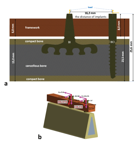
Figure 4: a: 3D model of highly atrophied mandible with the framework fixed on the BI and bicortical implant (BCI) with the corresponding occlusal forces and its vector components in three basic directions; b: Geometry and dimensions of the mandible with the BI, BCI and framework used in FEA.
The first case corresponds to the model situation of BI located in the zone of the 1st molar. The second pillar of the framework-the 1st premolar, was located in the preforaminal part of the mandible. The 2nd premolar was replaced with a pontic. The atrophy in the edentulous molar alveolar ridge was modeled by 2 mm reduction of the height of the mandible from 17 mm to 15 mm and by changing the horizontal width of the crestal region. The crest width was 5 mm in the crestal region while it was 8 mm in the 1st premolar region. The width of the basal parts in the corresponding areas was 12 mm. The thickness of compact bone was assumed to be 2 mm in the whole model. The length of the model of the mandible was 33 mm.
The total length of the tooth was 22.6 mm including the crown 9 mm long [53]. The framework ran parallel to the occlusal plane, causing a variation of the gap between the bone and the framework in the molar and premolar zones. The total height of the model system was 26.2 mm. The distance between the apex of the crown and the center of the neck of BI was 16.2 mm. The model of mandible assumed a homogeneous isotropic material with a density of D2.
Occlusal forces in the whole system were modeled by acting simultaneously in two points - at the top of the crown and in the middle of the BI neck at a distance of 2.4 mm above the surface of the framework (to account for the thickness of the future crown on the framework). BI was subjected to a vector force F = 256.37 N, analogous to the case of individual BI described in 2.1. In accordance with the distribution of the load in the premolar section, the force acting on the tooth was by 30-50% lower than in the BI area. Thus, the total force on the crown of the tooth was F = 118.2 N and it acted under an angle of 75o to the occlusal plane. Its components in the facio-lingual, axial and disto-medial direction were Fx =17.1 N, Fy =114.6 N and Fz =23.4 N, respectively (Figure 3).
The second model describes the case of unilateral or bilateral edentulous areas connected with a remaining frontal arch which was shortened to the level of the canine tooth. The case was applied to the uniformly atrophied alveolar bone in vertical and horizontal directions in the molar and premolar areas. The modified BI was located in the 1st molar area. The BIC was located in the zone of the missing 1st premolar. The framework was attached to BI and BCI. The distance between the centers of BI and BCI was 16.2 mm. The geometry, dimensions and properties of the bone of mandible also corresponded to the atrophied part in the BI region in Figure 3. The length of the model was 33 mm, the height of the bone 15 mm, the width of the crestal and basal part 5 mm and 12 mm with a total height of the system 25.6 mm. The model of mandible also assumed a homogeneous isotropic material with a density of D2 and a compact thickness of 2 mm. The occlusal forces acting on the whole system were identical as in the first case (Figure 4).
Figure 5 shows the geometry and dimensions of the modified BI, premolar and BCI, respectively. The morphology of the premolar was taken from our previous work [38]. The commercially available bicortical endosseal implant (grade 5, type SVMB 3,0-14D, Martikáň, SR, CE 1293.40042 / 101/1/2009 / CE (ISO9001)) has a length of 14 mm, its diameter is 3.0 mm neck area, in the thread area 2.0 mm and the thread depth is 0.5 mm. The BCI was screwed into the basal cortical bone up to a depth of 1 mm. For modeling purposes, its supraosseal part was extended up to 8 mm. In both cases, the framework was configured with a cross section of 6 mm x 6 mm and a length of 33 mm. The framework, BI and BCI were made of titanium alloy TiAl6V4.
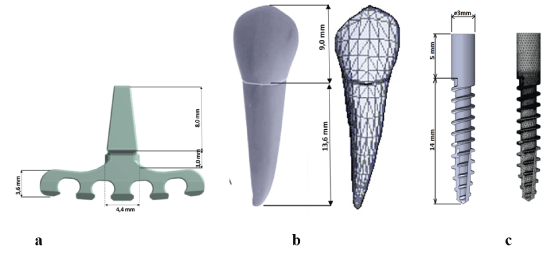
Figure 5: Geometry and dimensions of a: Modified BI, b: Premolar and c: StandardCommercial BCI used in the models for FEA.
FEA was performed in the same way as in the case of free-standing BIs. The output stresses in BI, BCI and tooth connected by a framework were compared with the yield stress of the corresponding materials as well as with the values obtained on the free-standing implant.
In Figure 6, the distributions of von Mises stresses in BI for both types of connection are compared. The stresses were concentrated along the edge between BI surfaces in the mesio-lingual and distovestibular directions of the neck. Since in both cases these values exceed the strength of the alloy by about 1.7 times, a locus minor is resistance would be imminent.
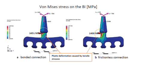
Figure 6: The distributions of von Mises stresses on the BI surface under load in the case of a: bonded connection (max. 1451 MPa) and b: frictionless connection (max. 1400 MPa).
The von Mises stress distributions in Figure 7 illustrates situations in the cortical bone. The stresses were concentrated in the compact bone and the contribution of cancellous bone was negligible. The highest stresses were generated in the crestal zone attached to the implant neck in mesio-distal direction. Despite these stresses were much lower (2-4 x) than the maximum tensile stresses in the neighboring BI neck, they are still greater than the strength of the bone. The maximum stresses were concentrated at the crestal medial margin of compact bone in an osseointegrated case and in the case of immediate loading, the stresses also concentrated in cortical bone in the distal corner of crestal margin.
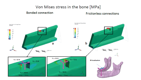
Figure 7: The distributions of von Mises stresses in the compact bone under load in the case of a: bonded connection (max. 573 MPa) and b: frictionless connection (max. 517 MPa).
The highest von Mises on BI surface and in the adjacent cortical bone were summarized in Table 2 together with the stress components Fy , Fx, Fz in the axial, buco-lingual and disto-medial direction. The comparison of these values with the corresponding yield stresses from Table 1 implied that the maximum stresses would most probably result in deformation of BI as well as in the destruction of the compact bone. Based on the current analysis it seems that the only efficient way for the reduction of von Mises stresses in the neck of BI and in the adjacent bone would be a modification of the shape [48] and increase of the cross section of the neck.
| Von Mises(MPa) | ||||
| 3D | Fy=240 N | Fx=50 N | Fz=75 N | |
| Rigid connection (BI) | 1451 | 115 | 691 | 707 |
| Frictionless connection (BI) | 1400 | 173 | 690 | 685 |
| Rigid connection (bone) | 573 | 66 | 281 | 313 |
| Frictionless connection (bone) | 517 | 93 | 353 | 212 |
Table 2: A comparison of the highest von Mises on the blade implant surface and in the cortical bone at the total load and under the separate action of the individual components Fy , Fx , Fz in the axial, buco-lingual and disto-medial directions.
Figures 6 and 7 clearly demonstrated that the maximum von Mises stresses were generated in the narrowest area of the BI neck. To reduce them, an increase of the cross section there would be necessary. Therefore, the neck dimensions were increased from the original 2.8 mm × 1.60 mm (Figure 1) to 4.40 mm × 1.60 mm. The size of such neck would still be within the range of diameters of commonly used RFI (3.5-4.5 mm). Additional contribution to the reduction of the stress concentration at the corners of the neck was obtained via increase the corner´s radius of the neck corner to 0.8 mm (Figure 8). Since the maximum stresses in the basal region of the blade part were significantly lower than the yield stress, the height of the blade part can be reduced simultaneously with the increase of the neck cross- section. This would widen the possibilities of BI applications in the cases when the distances of the inferior alveolar nerve from the crestal edge of the alveolar bone are less than 4-5 mm. The height of the ridge part of the blade was increased in the critical area by means of an introduction of curvature with a radius of 5 mm. The other dimensions of the neck have been preserved.
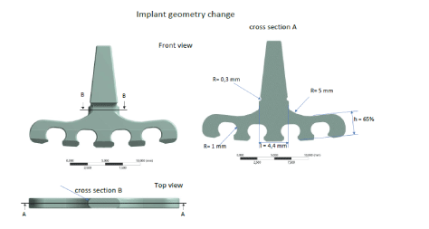
Figure 8: Modification of the geometry of the standard BI shape: the width of the neck was increased from 2.8 mm to 4.4 mm, the rounding to 0.8 mm and the height of the blade ridge was reduced by 35% to 3.575 mm. The cross section of the ridge part of the blade was increased via introduction of curvature with a radius of 5 mm.
The FEA distribution of von Mises stresses in the osseointegrated and immediately loaded cases are visualized in Figures 9a, 9b. The maximum stresses in the critical zone between neck and blade ridge were reduced from 1451 MPa to 729 MPa in the case of osseointegrated BI and from 1400 MPa to 721 MPa in the case of the immediate load. Thus, the shape modification reduced the maximum von Mises stresses below the yield stress values (730 MPa) in all cases. The possibility of plastic deformation of the BI material was eliminated both in immediate and delayed loadings. Thus, modified BI was used in further analyses.
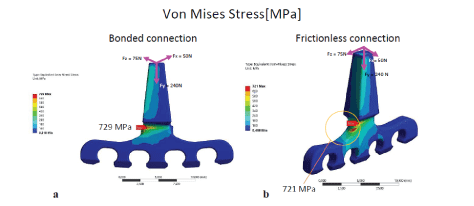
Figure 9: Comparison of von Mises stresses on the BI surface at a bonded connection (a) and at a frictionless connection (b) in BI with a reinforced neck and transition from the neck into the ridge.
Figure 7 and Table 2 indicated that the maximum von Mises stresses in the bone were significantly lower than in the BI. Since the corresponding stresses in the modified BI were dramatically reduced, the maximum stresses in the cortical bone would be also much lower. Thus, the stresses in the bone were considered to be not critical and the focus was concentrated only on the BI.
In the subsequent step, FEA was performed on the framework specified in Figure 3. Figures 10a and 10b illustrate stress distributions in immediate and delayed loadings. They are very similar and the difference is only in the maxima of von Mises stresses. They were concentrated in the corner of the transition from BI neck into the blade section. Relatively high stresses were also generated at the top of the BI superstructure, probably due to the deformation of the framework resulting from different loads in the molar and premolar areas.
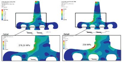
Figure 10: Von Mises stresses distributions in the blade implant in the case of a framework connecting modified BI and tooth and in a-bonded (osseointegrated) connection with compact bone (max. 276 MPa); b-frictionless (immediately loaded) connection (max. 226 MPa) with the compact bone.
Von Mises stresses on the tooth surface (Figures 11a,11b) were concentrated in the neck area in both cases.
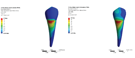
Figure 11: Von Mises stresses distributions on the tooth in the case of a framework connecting modified BI and tooth in a: bonded connection (max. 27 MPa); b: frictionless connection (max. 20 MPa) with the compact bone (yield stress of cement -29 MPa, dentin 50-75 MPa [4]).
The stress distribution in the adjacent compact bone reflected the distribution in the cervical part of BI however, with a slight shift of the maximum distal to the direction of the force component Fx (Figure 12).
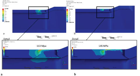
Figure 12: Distribution of von Mises stresses in the compact bone adjacent to the modified BI in the case of a framework connecting modified BI and tooth in a-bonded connection (max. 113 MPa); b-frictionless connection (max. 145 MPa).
Since the stresses on the premolar were approximately 10 times lower than on the BI surface and the corresponding stresses in the cortical bone are usually only half of the stresses on the tooth, their value with respect to bone strength would be negligible and therefore, it was not considered.
The distributions of von Mises stresses in the modified BI and BCI in the second framework system were visualized in Figure 13 and 14 for the imminent and delayed loading, respectively. The highest stresses in the osseointegrated case (Figure 13) were generated on the distal part of the BI superstructure in the area of the connection with the framework, regardless of the bonding level. However, because the superstructure is fixed in the framework, these stresses would not be significant in terms of damage. Another zone of stress concentration was observed in the distal region of the neck.
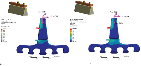
Figure 13: The distributions of von Mises stresses in BI in the system consisting of a framework with modified BI and BCI in the case of a-bonded (maxima of 206 MPa and 426 MPa, respectively) and b-frictionless connection (maxima of 214 MPa and 389 MPa, respectively) with the bone.
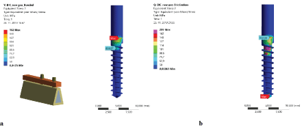
Figure 14: The distributions of von Mises stresses in BCI in the system consisting of a framework with modified BI and BCI in the case of a: bonded (max. 162 MPa) and b: frictionless connection (max. 299 MPa) with the bone.
The comparison of the distributions of von Mises stresses in the BIC (Figure 14) showed significant differences depending on the type of connection. In frictionless case, stresses were generated in the apex, in the neck area and in the first two threads of BCI. In the case of BCI bonded to the bone, stresses were concentrated only in the neck. The stresses in the first thread were small and no stress concentration in the apex was detected.
Table 3 summarizes the highest von Mises stresses in blade implants and BCI from the current FEA calculations for both types of bonding and framework cases. The corresponding values obtained on freestanding original and modified BI are also shown for comparison. Table 3 also shows analogous stresses in the cases of the framework attached to the BI with the original shape and the tooth (*) and BCI (**) which were also calculated, however, intentionally avoided in the Results.
| Maximum von Mises stress (MPa) | ||
| Location (case) | Delayed (osseointegrated) bonding | Frictionless bonding (immediate loading) |
| Initial(original) BI solo | 1451 | 1400 |
| Modified BI solo | 729 | 721 |
| Modified BI (+framework + tooth) | 276 | 226 |
| Modified BI (+framework + BCI) | 206 | 214 |
| BCI (framework+modified BI) | 162 | 299 |
| Initial(original) BI (+framework +BCI)* | 503 | 490 |
| BCI (+ framework+initial(original)BI)** | 181 | 841 |
Table 3: The values of the maximum von Mises stresses on the modified BI as well as on BCI in both types of bonding and framework attached to the 1st premolar and BCI, respectively, and on the free-standing original and modified BI.
Despite the stresses were always concentrated in the neck of BI, stress maxima can be significantly reduced by proposed BI shape modification in both types of connections (see Figure 6 and 9). In contrast to the stresses in the original BI, the maximum stresses in the modified BI were in the range 720-730 GPa, that is below the yield stress of Ti6Al4V alloy (880 MPa to 920 MPa [46]- see figure 15). It means that plastic deformation of modified BI would be avoided with sufficient factor of safety.
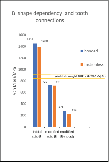
Figure 15: Graphical comparison of the maximum von Mises stresses in free-standing BI with original shape, free-standing BI with modified shape and in modified BI attached to the framework and 1st premolar in the cases of immediate and delayed loadings.
Table 2 indicated that the level of concentration of von Mises stresses is controlled by the load components in non-axial directions. The use of more compliant materials for BI, e. g. pure titanium CP - Ti Gr. 3 with the yield stress of ~333 MPa would be contra-productive and at the account of factor of safety. Indeed, the Strietzel’s investigation [54] of potential benefits of bending of supraosseal part of BI made of softer alloy in the case of unfavorable inclinations of alveolar bone revealed the formation up to 100 μm long cracks already at <20° bending. At 30° bending, cracks were much larger which dramatically increased the probability of implant failure and simultaneously promoted plaque accumulation in the cracks [54]. Thus, stiffer materials for (modified) BI are necessary.
At the same time, the maximum von Mises stresses generated in the adjacent compact bone, despite their significant decrease after BI shape modification (Figure 12), were in the range of yield strength of the compact bone (see Table 1). Thus, cracks prevention may still require further stress reduction for solo BI applications.
It should also be noted that the maximum von Mises stresses in BI after immediate loading were always slightly lower than in the osseointegrated case. The reason seems to be the consequence of possible of micro-movements allowed in non-integrated BI under occlusal forces. In the case of bonded connection, the accommodation of load via micro-movements would be dramatically restricted and subsequently, the maximum von Mises stresses were (slightly) higher.
In the case of framework on BI and tooth, the maximum stresses in the modified BI were reduced below 30 % of the yield stress in comparison to free-standing modified BI (Figure 15). On the tooth, the stresses were only 68% of the yield stress of cement and 26-40% of the yield stress of dentin. In our earlier study [38] it was shown that the compact bone is bearing majority of the occlusal forces (up to 90% of the load). Therefore, further consideration of stress transfer to cancellous bone can be fully omitted. Evidently, the solution offers high factor of safety.
As it was mentioned above, a healthy tooth is never firmly attached to a compact bone. The connections between the compact bone and tooth (and BI) occur via periodontal fibers, which provide certain flexibility. The current FEA model was not able to capture properly such conditions of the tooth-bone interface and addressed only ideally fixed or absolutely frictionless connections. Despite that and similarly as in the solo BI case, lower stresses were predicted for immediate loading case. This result corroborates the assumption of stress accommodation by BI micro-movements and flexibility of the teeth. The stress concentration in the upper part of the BI superstructure (Figure 10) is the consequence of the mobility of the BI and the tooth in the frictionless connection. However, these stresses were not critical to BI, bone and framework.
The stresses in the case of framework on initial BI and BCI were around 500 GPa both in bonded and frictionless connections (Figure 16). It is well below yield stress of Ti alloy. When modified BI in the framework was used, the maximum stress was further reduced to less than 60% of the previous case regardless of type of connection. Thus, the framework based on modified BI and BCI provides a solution with safety factor further improved compared to the framework fixation on modified BI and tooth.
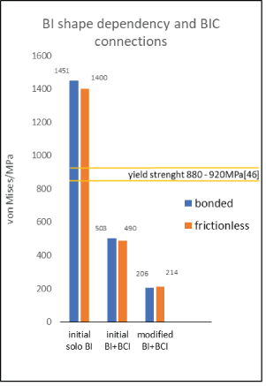
Figure 16: A comparison of the maximum von Mises stresses in free-standing BI with original shape, original BI attached to BCI via framework and in modified BI attached to BCI via framework in the cases of immediate and delayed loadings.
It should be noted that in the framework fixed on original BI and BCI and frictionless connection case, stress concentrations on BI surface occurred. The reason seems to be related to higher lever and torsional forces developed in the immediately loaded BI, which are transmitted to the neck and to the 1st and 2nd threads of the BCI. When original BI was replaced by modified BI, the stress in the threaded part of the BCI increased, but they remained comparable in the neck area due to easier micro-movement of the non-osseointegrated BI. BCI embedded in the basal cortical bone does not allow such micro-movements and the difference in the zone of BCI and BI acts as a lever generating tensile stresses in the threaded neck of BCI.
The yield stress of cortical bone varies from 42 MPa to 176.3 (± 13.1) MPa, depending on the thickness, bone density, age, sex, etc. [55]. Stress maxima in the adjacent cortical bone in the framework anchored on the modified BI and tooth were roughly half of the maximum stresses in the BI. Assuming similar ratio in the case of framework on BI and BCI, the stresses in the bone would be around 100 MPa. This seems to be well within the range of yield stress of the bone. These observations comply with our earlier measurements on free standing BCI [38]: at the maxima of the von Mises stress in BCI, the stresses in the adjacent cortical bone were around half of those in the BCI. When BCI was attached to modified BI via framework, the stresses decreased to only 299-162 MPa, the stresses in the bone would decrease correspondingly by half and the possibility of cortical bone damage would be practically eliminated.
Under the load (occlusal forces) corresponding only to 40% of the level of forces required to reach the yield point of the cortical bone (assuming enosseal implant with the diameter of 3.0 mm, alveolar bone width of 5.0 mm, width of the crestal compact bone in the neck part of BCI in the facio-oral diameter only 1 mm) [21], an approximation applied to BI with the facio-oral diameter of 1.6 mm suggests, that the yield limit of the bone cannot be exceeded even if the residual ridge crest in the facio-oral diameter would be only 3.6 mm (bone 1 mm + BI 1, 6mm + bone 1mm). This is the indication width of the modified BI.
The experience confirms that despite large variations in bone vitality great depending on age, health status, etc., reflected in wide range of its yield stress [45], mechanical damage of the bone occurs extremely rarely, most probably due to stabilizing effect of the blade part. The above results emphasize advantages of application of BI in extreme ridge atrophies of the mandible and its connection via framework with another enosseous implant located in the interforaminal area in delayed and immediate prosthetic protocol.
The problems of an implant with a tooth in one bridge connection were discussed in the literature for several decades. The arguments against such connection were based on the risk for the implant and for the abutment tooth [56-58]. On the other hand, long-term clinical success has been reported for the fixed partial prostheses with implant (osseal)-dental transfer of occlusal forces without negative consequences for the tooth or periodontium although it should not be the first choice method [59,60]. Such connection did not increase the risks compared to fixed prostheses attached the implant - implant, especially in the connections with the tooth with a good biological factor, respectively with two teeth connected with one implant or two implants and one tooth [40]. Despite that, the connection of the osseointegrated implant with load transfer to the compact bone and the tooth transferring the load to the alveolar bone via periodontal tissues still remains a dilemma [61,62]. The cases of successfully osseointegrated Linkows’ blade-vent implants supported fixed partial dentures at the mandible are reported after long periods [63,64]. Current study indicated that the difference in stress values generated on the modified BI attached to the BCI was reduced by 34% in comparison with the modified BI attached to tooth in bonded case and by only 5.6% in frictionless case. In an implant rigidly connected to a bone [65], without absorbing the load through the periodontal ligament, such as a tooth, tension is generated in the neck region due to vertical pillar movement and an increase in nonaxial and rotational forces due to the fixed partial denture levels occurs [27,66]. In the case of framework on immediately loaded BI and tooth, the micro-movement on BI would have an undesirable effect on the process of osseointegration of the BI. Therefore, a prosthetic load on the framework connecting BI and one pillar would be preferred only after the end of osseointegration.
The results of current study emphasize the benefits of unconventional solutions for framework attached to blade implant and tooth or SDI, respectively, in the treatment of extreme atrophies of the residual ridge crest distal parts of the mandible, especially when standard implant systems are not applicable.
FEA of the transfer of the occlusal load to free-standing BI and adjacent bone and evaluation of the distribution of von Mises stresses on the framework anchored in a mandible with significant degree of atrophy with tooth and SDI (BCI) after application of immediate and delayed loads showed that von Mises tensile stresses in the cervical part on the BI surface can be significantly reduced when the shape of the BI was modified (cross sections increased).
Shape modification involving the reduction of the height of the blade part facilitates implantation treatment when the distance by the course of the inferior alveolar nerve and the crestal margin is only 5,0- 5,5 mm. The maximum stress values on the free-standing modified BI surface were well below the yield stress of Ti6Al4V and within the range of compact bone yield stress.
Further benefits in stress reduction were demonstrated in the cases of framework anchored on BI and tooth or on BI and BCI with the last case offering the higher factor of safety. Delayed loading is preferred in the case of framework anchored on BI and tooth because it generates the lowest stresses and both immediate and delayed loading are acceptable in the framework combined with BI and SDI (BCI).
The authors declare no conflict of interest. The funders had no role in the design of the study; in the collection, analyses, or interpretation of data; in the writing of the manuscript or in the decision to publish the results.
Download Provisional PDF Here
Article Type: RESEARCH ARTICLE
Citation: Kučera J, Lofaj F, Šimůnek A, Németh D (2022) Finite Element Analysis of Blade Implants and their Modifications as a Nonstandard Solution in Toothless Atrophied Alveolar Crest of Mandible. Int J Dent Oral Health 8(3): dx.doi.org/10.16966/2378-7090.394
Copyright: © 2022 Kučera J, et al. This is an open-access article distributed under the terms of the Creative Commons Attribution License, which permits unrestricted use, distribution, and reproduction in any medium, provided the original author and source are credited.
Publication history:
All Sci Forschen Journals are Open Access